Tascam US-16x08 Teardown / Attempted Repair
Some time ago, I wrote about my US-16x08 acting up. So, some time last fall, I decided to open it and see what might be the cause. This is mostly a teardown “manual”, some photos of the chips in there, and some ranting about cheap choices. Oh, and if you are impatient: I didn’t manage to fix it, but I made a workaround at the very end.
Motivation
Headphone output is bad. Lots of noise, harmonics, left-right was unbalanced at low levels, and I could only use low levels, because at more than the first 2 mm of the dial, it would blow my ears out. Also, occasional software/firmware(?) hiccups, but nothing persistent.
Teardown
Every screw in there is some kind of crosshead (Philips) head, but there are a couple of sizes. I highly recommend an electric screw driver to not go insane, plus a normal one to not break too many screws.
Screws, So Many Screws
First, remove the desk stands or rack mount (whichever you have put on). Those are the only non-crosshead screws, but surely you remember where you put the hex key that it shipped with, right?
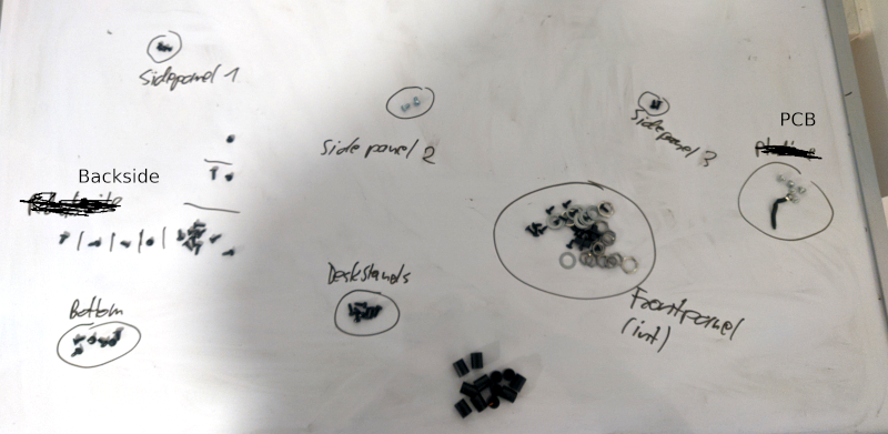
Then, remove all the screws that are visible on the outside. Take a note of which screw goes where. I put mine on a flat dry-erase board and wrote their origin next to them. Don’t forget the bottom side.
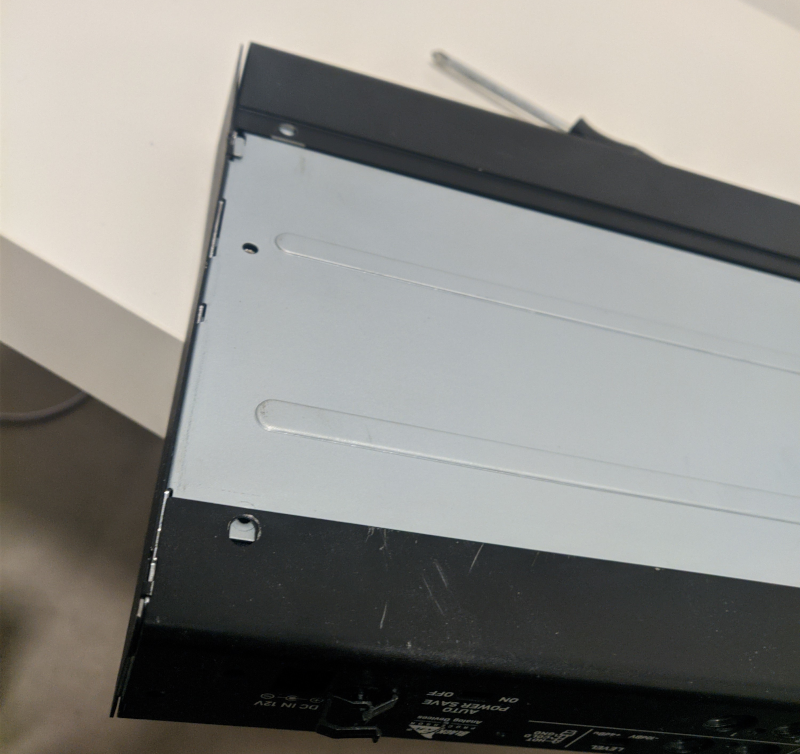
If you’ve done this, you should be able to slide the shell open like this. It might need a bit of wiggling around.
This should give you access to quite a few of the breakable parts, like the DC jack.
Even More Screws
Start by peeling off the knobs on the front.
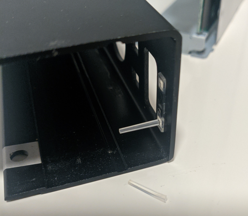
Now, a slightly tricky part: Slide and wiggle the front plate off without breaking the two light guides for the LEDs.
Guess what, I failed this step. However, a drop of clear glue and a steady hand can easily fix this.
Below this cover, you’ll find… more screws! Yay! Remove all of those, and don’t forget the thin nuts and washers for each dial.
Next part, the metallic bracket/sheet. First, remove the screws left on the sides:
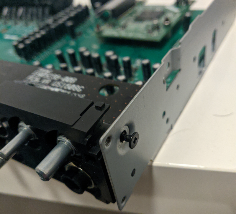
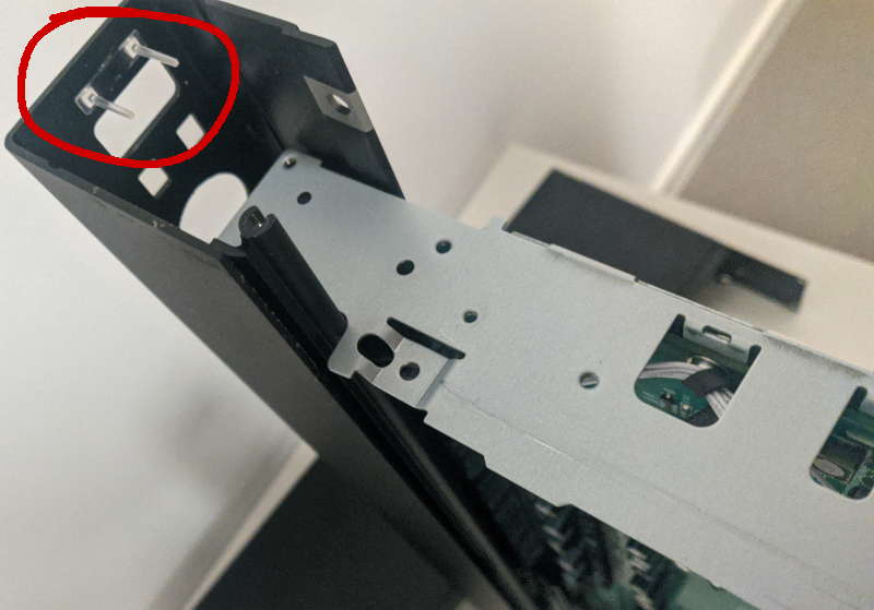
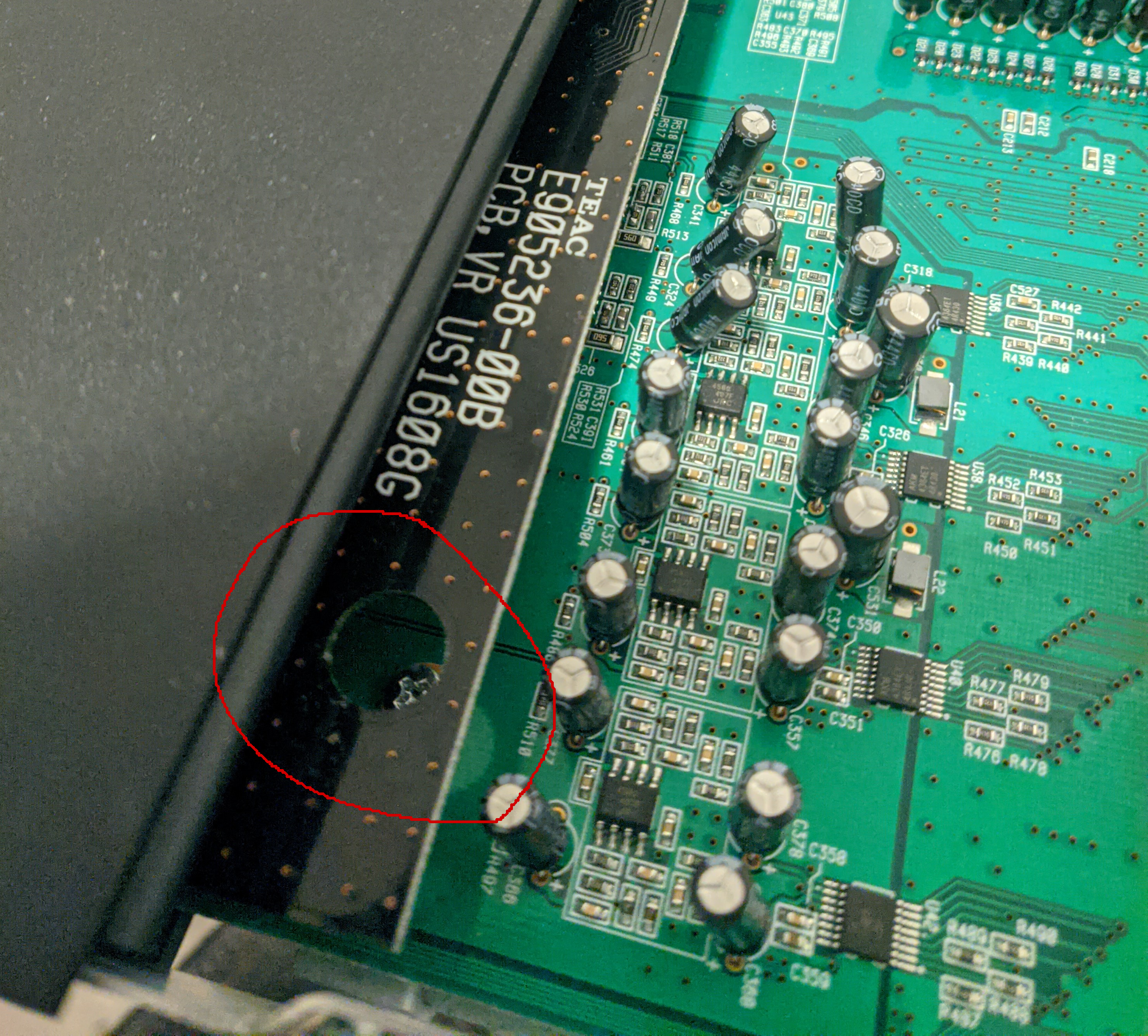
Then, remove all the silver-colored screws holding the main PCB in place. Besides the obvious ones, don’t forget the two hidden ones here…
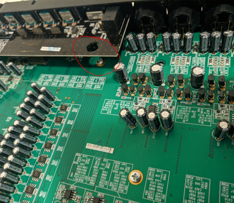
…and here:
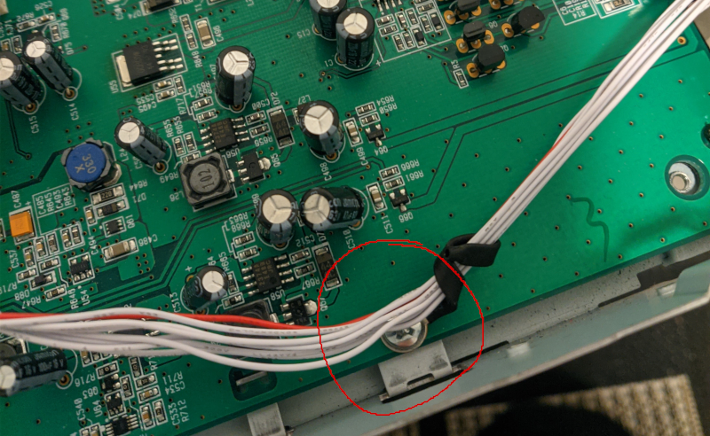
This includes the common mode choke / “cable organizer” screw. Once that is out of the way, you can unplug the cable it was choking and take off the metal bracket and the front plastic cover.
Results!
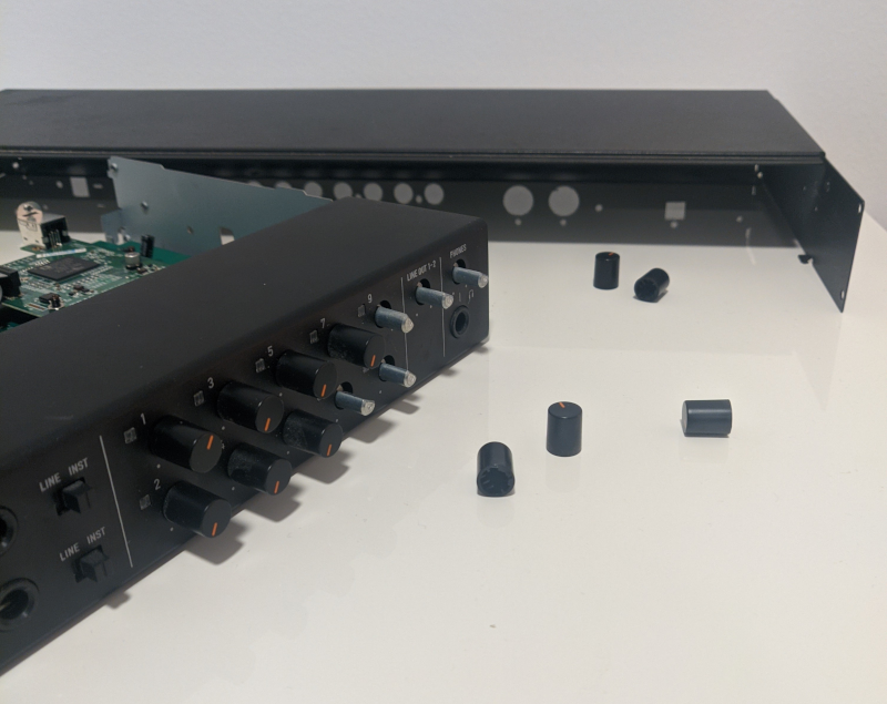
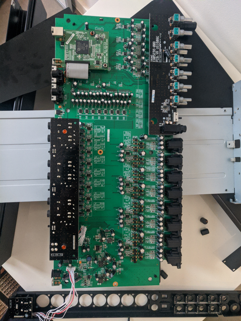
Congrats, here you have it, all disassembled:
And all the small parts that came out of it:
I found it easier to cut the plastic sheet on the bottom than to undo all those little plastic clips. It’s only for insulation, so a few well-placed strips of duck tape will fix it. If you need to, you can squeeze the plastic clips holding the two large auxiliary PCBs with small pliers to get them out.
Internals
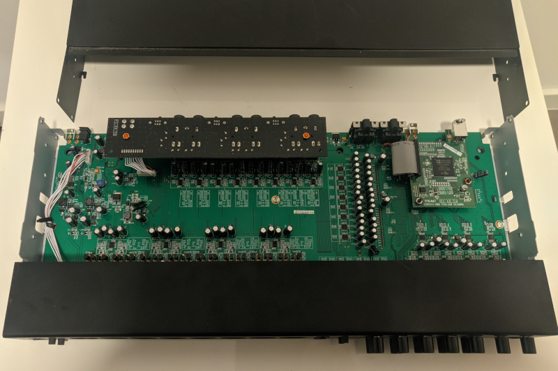
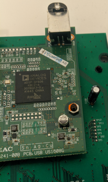
Since you might just be interested in what’s inside, here are some pics. The main chip is an ADSP-BF606, which does all the DSP mixing and (I assume) communication with the host.
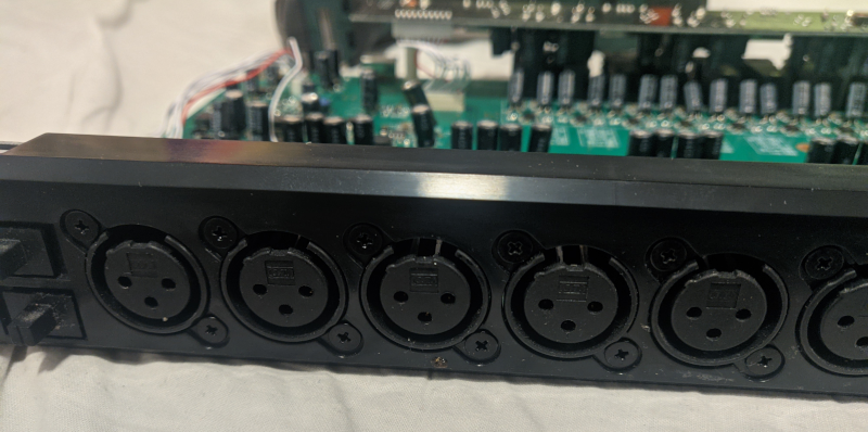
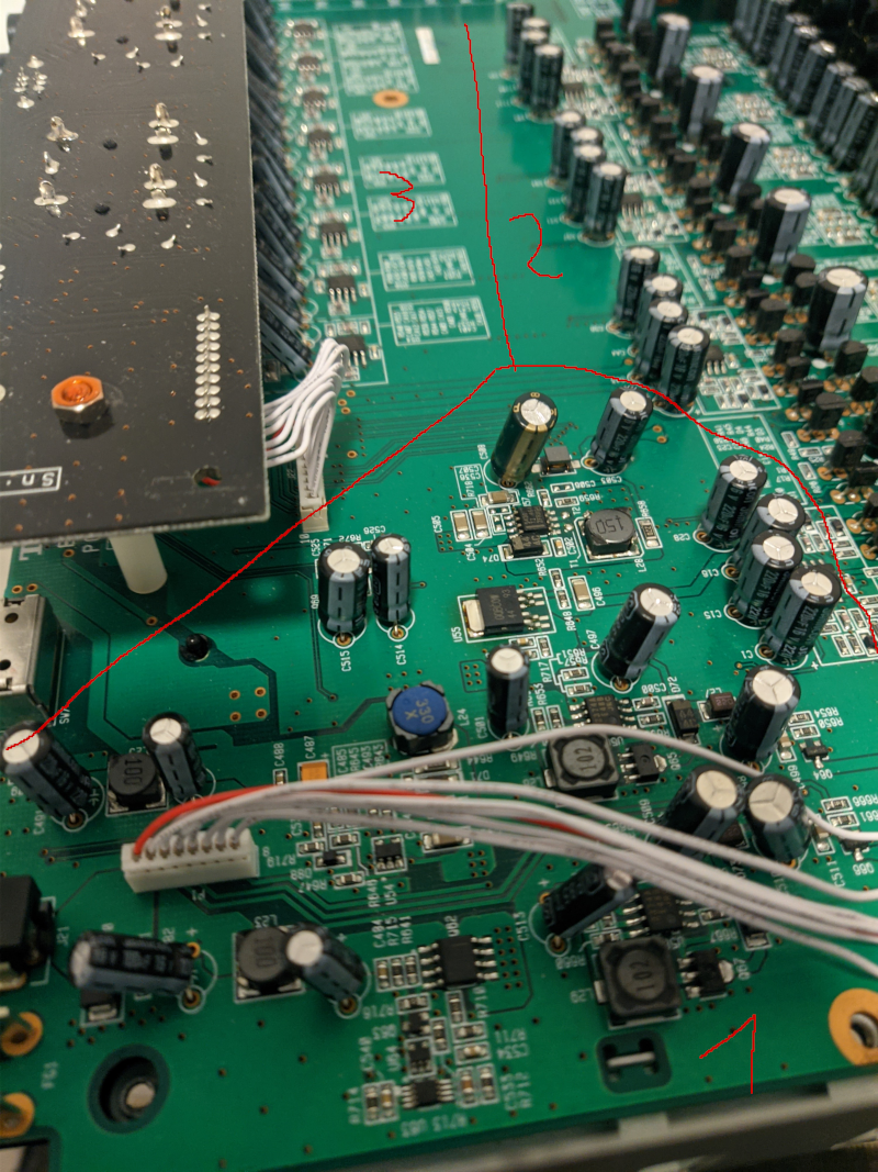
Here is a shot of the other side. Part 1 is the power supply. Yes, it has switching converters, but they are all switching well above a couple 100kHz. IIRC the main one runs at 1 MHz. So, no problems there. Part 2 shows the advertised discrete headphone amps, which are, in fact, made with discrete transistors. Part 3 is the backside with some Opamps and the daughter board to fit more connectors.
Trying to Diagnose the Headphone Output
Here is a rough diagram of the headphone output:
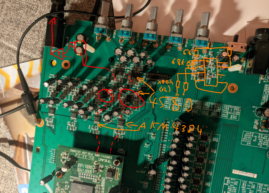
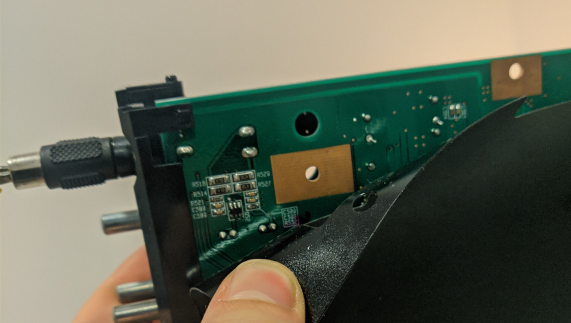
The DACs are AKM4384, budget chips but in theory more than capable to deliver a clean signal. Then, some JRC4580 opamps. They really like those opamps, they are everywhere. My guess is that they bought a warehouse full of unwanted opamps and now they have to get rid of them somehow. Finally, on the backside, just below those stylish black-orange caps, is a small unknown chip which I guess is another amplifier to deliver some more juice. Here it is:
All in all, the headphone side looks like they cut some corners, but overall knew what they did. There are large caps everywhere, everything looks nice and tidy, and they put quite a few resistors in parallel to the output so that (my guess) whatever happens at the output would not influence the signal generation too much.
Sadly, the signal is distorted at every step. My first guess was that the Opamps are amplifying too much, but lowering their feedback resistor value only made things slightly quieter. I measured and tinkered and ultimately gave up. Maybe I could have replaced the caps, but this interface is not that old, and they all looked solid. My current theories are: a) the DSP sends bullshit to the DACs and/or configures them wrong, and b) the DACs are just broken internally. Sadly, I didn’t have the patience to capture and decode the communication, so I guess we’ll never know.
“Fixing” the Problem
To use more than the first 2 mm of the volume dial, I made a small dampener (and impedance converter), mainly based on this excellent site. Here’s the result. Yes, that is a Lego brick.
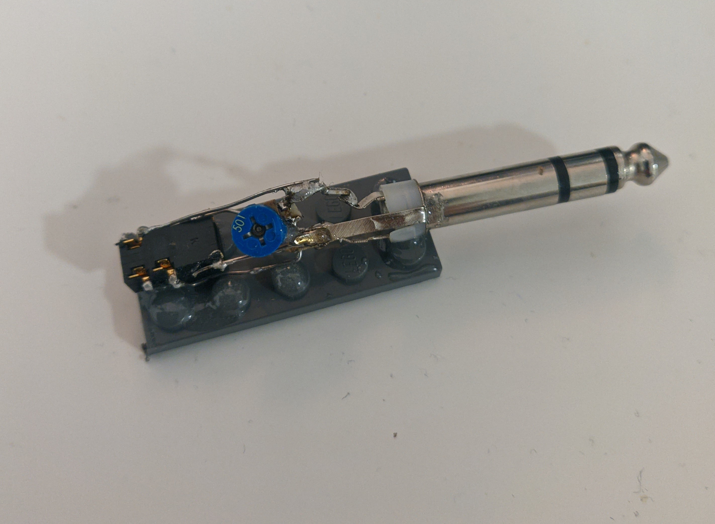
I can now use more of the volume dial, I avoid the very low end where the stereo channels are really unbalanced, and even my high-impedance high-efficiency “active” Bose QC-25 headphones are happy now. Sure, the noise is still there, but unless I can justify buying a new interface, this will do.