Current Build and Background
Making the Electronics
Alright, let’s get started.
Let’s Pick a Controller
After a lot of Internet, I decided to use PX4 as the flight controller software. The reason for that is that I did not find any cheap flight controllers that fit my needs. Since using some old 8 bit microcontroller would restrict me to obsolete software (and hey, it’s 2021!), the other hardware I’m familiar with is the Raspberry Pi. Conveniently, PX4 can run directly on the RasPi.
But wait, isn’t that bad?! How would you run critical realtime code on a Linux OS?!1!
Simple answer, I figured I don’t have to. I’m building a plane, not a multicopter, and planes have been flying (many still do) for decades without any fancy control loops. With a somewhat stable airframe, there is no reason why a few microseconds here and there would hurt anything. I finally settled on a RasPi 3A+, because I figured that a RasPi Zero would be too slow.
Adding an IMU
So, PX4 it is. A flight controller needs some data to work with, and usually the most important sensor is the inertial measurement unit (IMU). This is a fancy name for a combination of gyroscope, accelerometer and (optionally) magnetometer/compass. The IMU tells the flight controller if the plane is facing the right way, and it’s not, say, upside down and rapidly accelerating towards the ground (pro tip: avoid this situation).
The good news is that PX4 supports almost every sensor and scenario out there. The bad news is that the sensor I already have (BNO055) is not supported. Well, let’s put on our black hoodies and fingerless gloves then and get hacking!
Sadly, PX4 is pretty hard to get into, to a point where the official documentation recommends you to copy-paste an existing driver and mess with it until it works. After (way too) much time, I managed to squeeze the official Bosch driver into a PX4 Module. Currently (04.21) it’s not 100% finished, but it is stable enough that I will focus on the next steps.
Adding Some Actuators
Actuators are machine parts that do something. I want the plane to do something, so I’ll probably need some actuators.
I had a “Baby Orangutan B-328” lying around. This tiny chip combines an AVR processor (the kind they use in Arduinos) with quite a lot of peripherals. I originally wanted to use it as an ESC, but it didn’t work. The whole story is here, if you are interested.
Since I already have this board, I might as well put it to use for other stuff. The actuators of choice for moving control surfaces (rudder, elevator and so on) are servo motors, who are usually controlled by a PWM signal. As the AVR chip is not doing much work yet, I might as well use it as a PWM expansion board for the RasPi.
And since we are on it, the RasPi has no analog inputs, but the AVR has. So I’m going to use it for measuring the battery voltage (with a simple voltage divider) as well.
All those functions are implemented in this firmware, together with some bonus functions like an emergency low battery shutdown.
After previously dealing with all the high-level mess of PX4, programming on a simple, easy 8 bit CPU feels like a vacation. Why am I doing this again? Oh, right, for fun.
Wait, I need to make a PX4 driver for this, too?
Wait, I need to make like three different drivers?!
Power Train V2.0, Now With Real Power
Hint: If you plan on building something similar, just get a proper ESC in the first place. Don’t be like me, just spend some money and save a few days of your lifetime.
As you can read in the first flight logs, the original power train never really flew. Instead of trying to tweak it until it might just barely not crash, I lost patience and gave in to the “just buy a brushless motor lol” people. Sadly, this removes a big part of the scrap plane appeal. Oh, and it costs some money, too. But one good thing about the “throw money at problem until it goes away” approach is that I can have some other improvements, like a bigger battery to feed the power-hungry RasPi.
I figured to follow the old saying of “go big or go home” (well, technically, I am already home because of Covid, but.. you know what I mean). So I got a 15 A ESC with a BEC (that is how drone people call voltage regulators), a small brushless motor to turn those 15 A into rotation and a 2S 1300 mAh LiPo.
One issue with this is that I didn’t look too closely at the propeller and just got the first recommended prop for this setup. So I was a bit surprised when I got a massive 9 inch one, which is way bigger than I thought (insert that’s what she said joke of your choice).
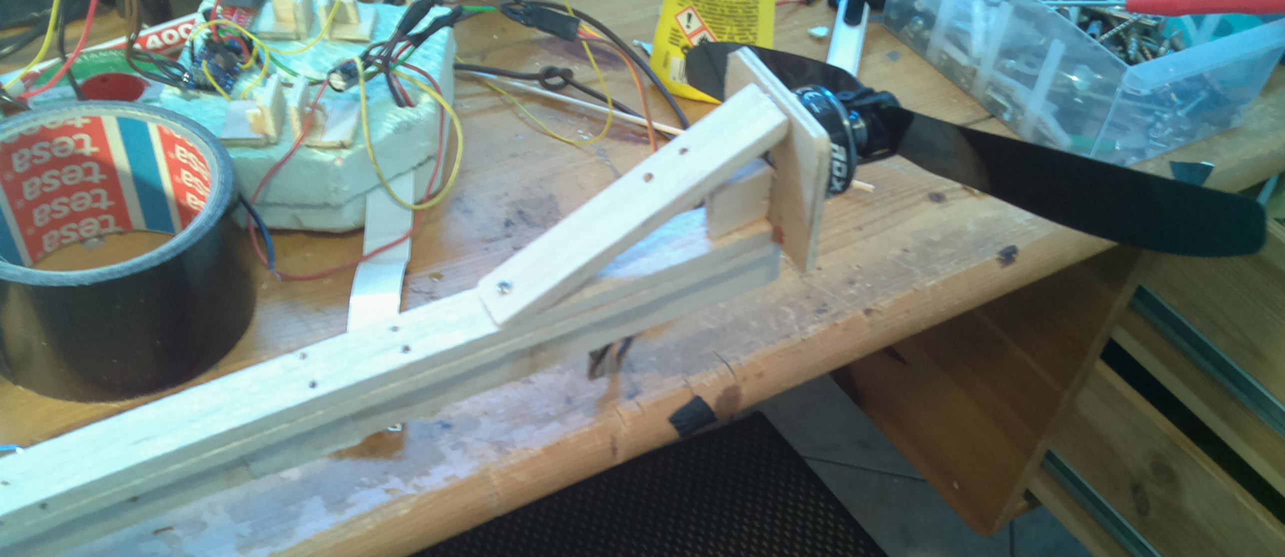
This prop didn’t fit on the original mounting column any more, which leaves me with two options: Either replace it with a random smaller prop that I have, or use this prop and re-design the prop mount. I decided to go for the latter and mount it at the very front of the airplane, for a slightly more conservative design. I went with the conventional “firewall” style mount and strengthened the front part of the backbone to withstand the additional force. While I was at it, I also reduced the wing angle of attack – I should have more than enough air flow now, and I don’t want to get in a stall and crash on my new, shiny motor. Note that the picture still shows the old pure-balsa backbone.
I can only hope that with all the mounting troubles, it will finally produce enough thrust (again, the dirty pun is left as an exercise for the reader).
Putting it all Together
I also figured I might want a barometer. The “good” PX4 sensor fusion module (ekf2) needs a height source to do its magic. Because of some delays in shipping, the first tests were made without it and with the “bad” sensor fusion module (attitude_estimator_q). I got a DPS310, which already has a PX4 driver (phew).
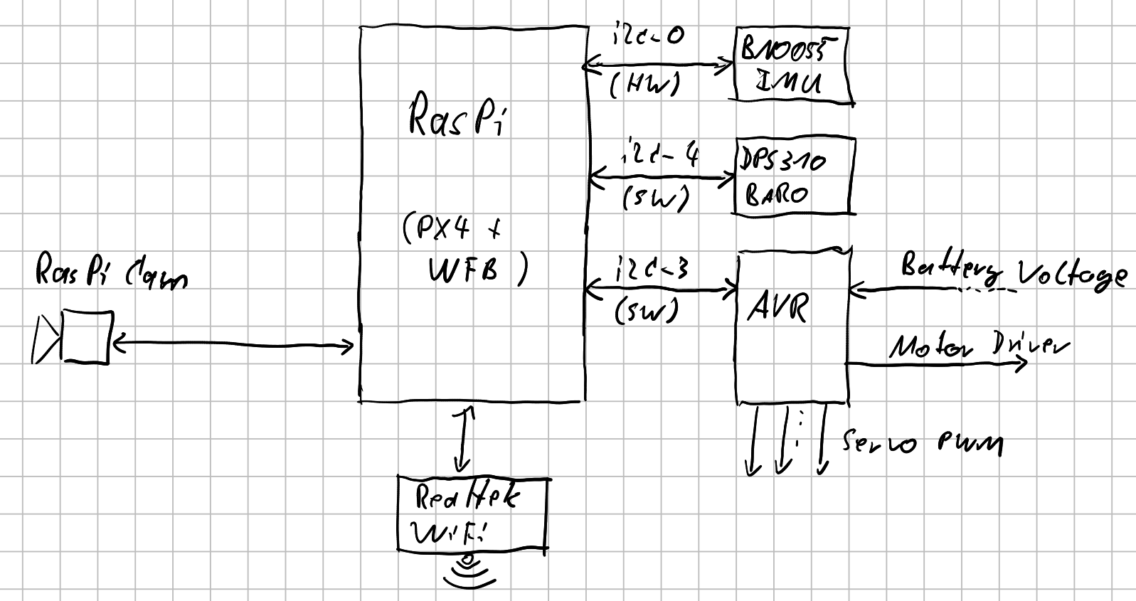
I also noticed that putting the AVR and the IMU on the same I2C bus caused issues, despite people claiming that it shouldn’t (insert something about scheduling and work queues here). Luckily, the RasPi has a neat little trick: You can tell it to use any two GPIO pins as software I2C. I figured it would be best to give the time-critical IMU the hardware I2C and put both the AVR and the barometer on their own software I2Cs. Of course I had to dig into the PX4 source make it use more than one I2C bus, but hey.. it works.
Here is the whole rat’s nest as a diagram, in case you made it this far:
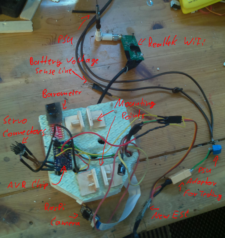
And here is a picture of the electronics test setup with the new ESC in place. Inside the green foam are the RasPi and the IMU, which is mounted directly to the RasPi connector. The picture is not quite up to date, but you get the general idea.
Making the Airframe
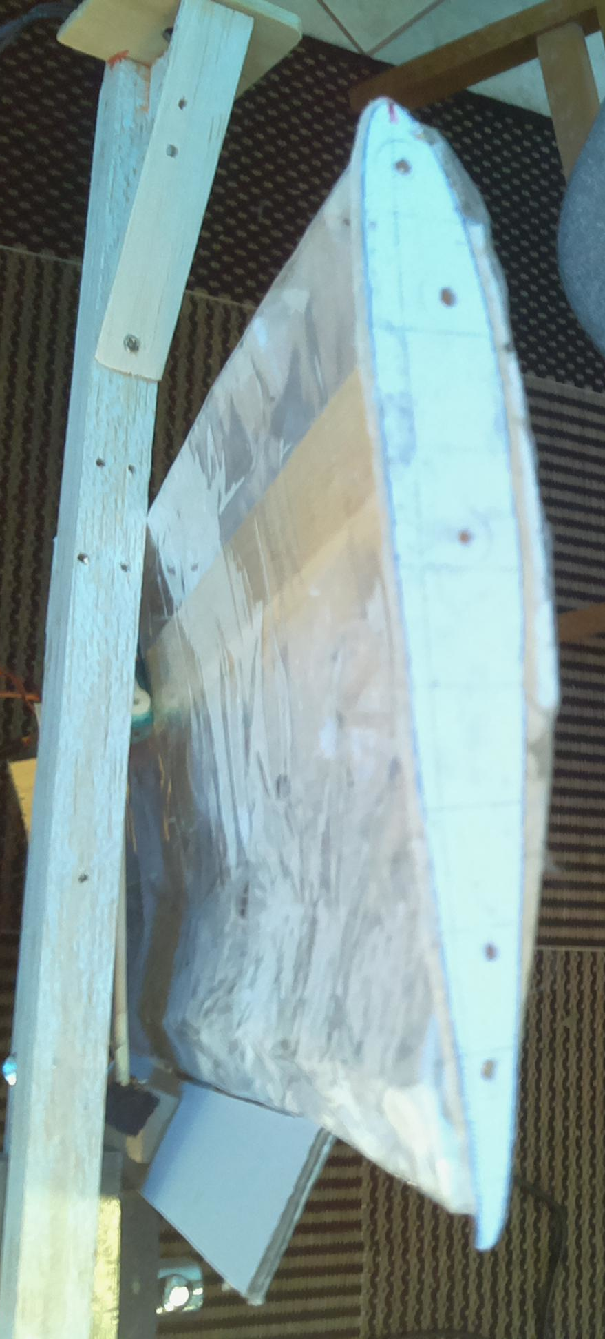
The wing is made of styrofoam that was cut into along the length and bent into something that resembles a Clark-Y profile if you don’t look to close. I then added a balsa wood bar for stability and wrapped the whole thing in package tape. Looking back, there are probably better ways to do this. On the other hand, package tape is cheap, and styrofoam basically costs nothing.
Here is the wing profile and the Clark-Y stencil I used. Close enough for me.
The rudder and elevator are made of styrofoam with shashlik skewers for stability (I totally didn’t use them to fix the rudder after stepping on it). All control surfaces are just cardboard cutouts attached by duct tape. Hey, I warned you about the duct tape.
After I gave up on balsa wood (see here for the learning process), I made the backbone out of a spruce bar of originally 4 cm x 2 cm, that I then cut down pretty crudely to about 2 cm x 2 cm. Then, I drilled a lot of holes in it to make it lighter. Much to my surprise, it still lasts. The tail is still on its original balsa piece (about 20 cm), which I glued to the main backbone for some extra length / leverage.
The controller nacelle is made of dense foamboard to protect the electronics. The AVR/motor controller (potentially creates lots of heat) and barometer (I forgot to make some space inside) were glued on top of it, but after a crash/redesign, I figured I might as well put them inside. It is detachable and can be moved forwards and backwards to change the center of gravity (note that I scrapped the mounting points in the picture and just screwed it on at some point). Because it went through a few changes, the nacelle is now mounted upside down. The biggest impact of this is that it required a lot of guesswork to find the right IMU orientation again. Also, the camera now goes on top (actually on top this time), to prevent it from hitting the dirt too much.
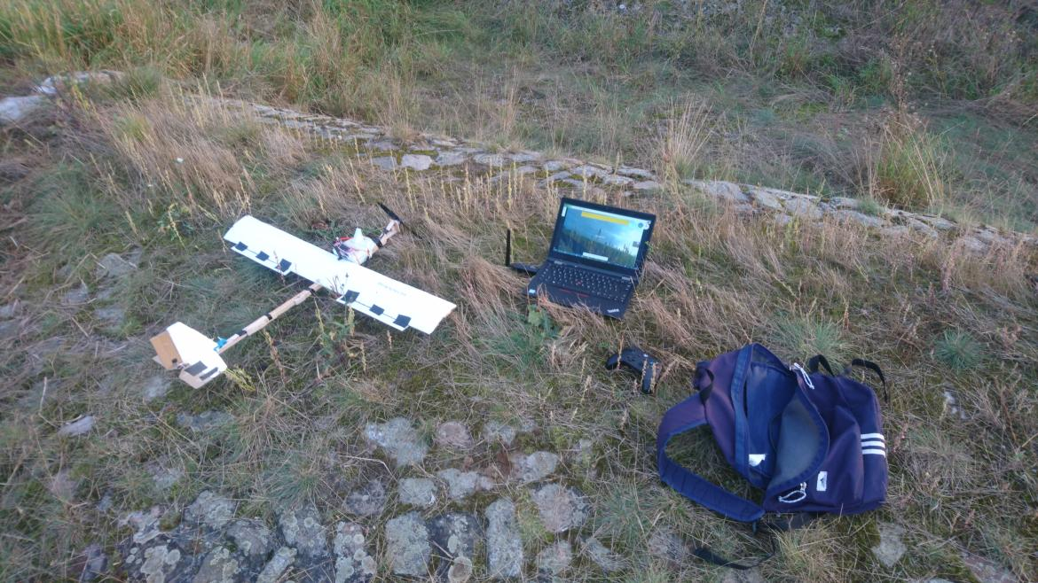
Here is a picture of the current setup:
Transmitter and Camera
Before the actual flying, let’s talk a bit about radios.
Usually, when you build a RC vehicle, you use a dedicated receiver that talks to a remote control on the ground. Then you maybe add an analog video transmitter for your camera.
We’re going to use none of that.
Poor Man’s HD Radio
Instead, what I already have is my laptop/tablet, on which I am writing this. I also have a pretty smart RasPi as a flight controller. With these two in mind, I found something called Wifibroadcast, which uses (you guessed it) wifi cards to transmit raw data instead of all the fancy networking stuff. Since it’s just using the regular wifi bands and since I’m not touching the output limits or antennas, it should be as legal as a normal hotspot. I would recommend against using it near other people’s wifis though, since it tends to kind of jam the wifi channel it uses, and people probably won’t like that.
Fun with WiFi Adaptors
My current setup consists of one (way too expensive) Asus USB-AC56
RTL8812AU together with the onboard Intel wifi (RX only) on the ground,
and then one Edimax EW-7811UAC (RTL8811AU) on the drone. If you
want to laugh read about my painful try-and-error, go
here.
There seems to be some undocumented feature with modern Intel chips that doesn’t allow packet injection in the 5 GHz band, so I made a hack for Wifibroadcast that forces it to only use the first adaptor as TX (instead of selecting the one with the highest signal strength).
On the drone I decided against throwing the internal wifi into the mix, although I tried out an interesting driver called Nexmon. Nexmon does all kinds of fancy stuff with the Broadcom chip, but sadly, no reliable packet injection. While I could probably do the same trick I did on the ground side, I figured I might want to have some other channel for easier debugging and internet. So for now, the internal wifi will only do regular, boring home wifi.
While the RTL8812AU is pretty famous with the “strange stuff with wifi” crowd, the RTL8811AU has worse receiver magic, in my case smaller antennas with less gain, and no configurable TX power. This means that the drone => laptop direction will start to drop data long before the laptop => drone will. In practice, the video will stutter before the remote control does, and I can very well live with that.
I am, of course, using the improved version of Wifibroadcast to glue PX4 and QGroundStation together. The video comes with a hand-made, all-organic gstreamer command that gets set up during my big “init everything” script. All in all, I get around 200 m meters of range using a (to my understanding, IANAL, see below) pretty sane interpretation of the wifi channel rules. Note that the 200 m are a line-of-sight value, it tends to drop dramatically if there are trees in the way.
Legal Stuff
It wouldn’t be the European Union that we all know and love, if it didn’t have any specific rules about, well, anything. Obligatory note, don’t take anything in this article for legal advice.
Did you really want to take legal advice from a guy who made a plane out of duct tape?
Surprisingly, the new EU drone law is pretty sensible and sounds like
a good compromise between hobbyists, commercial drones and security
concerns. Because my drone is just perfectly fitting into the 250 g
“free” category, I could just get flying. With the new motor and
battery, I am now definitely above the 250 g limit. I also want to add a
sensor capable of recording or transmitting personally identifiable
information (aka a camera), which means that I have to get a
bloody loicence, m8te anyway.
Taking the quick online test and getting a registration number was surprisingly painless – you can solve the test with some common sense alone, and when in doubt, it’s not like they prevent you from googling the answers.
On the wifi end, I am using channel 161. Digging through the EU regulation, I found an official-looking page that basically told me that, on these frequencies, as a generic “Short Rage Device (SRD)”, I have to stay below 25 mW EIRP and that’s it. I could go higher (up to several hundred mW), but then I would need to activate some kind of interference mitigation, and I have no idea how to even check for that. Conveniently, the mitigation spec says that in case of a collision, you need to be able limit yourself to 25 mW as well, which means that staying at 25 mW in the first place ist probably legal. To date, no angry radar operators have shown up. I know my home wifi router complains about weather radar kicking him off the air every now and then, but the radar tends to be on a different band. The biggest impact probably comes from the drone video stream anyway, and that tiny Edimax stick doesn’t have a lot of transmit power to begin with. Whatever you do, do your own reading and choose what looks the least criminal to you.
In general, the less trouble you get in, the better. So if you don’t annoy people (like on an open field far away from everything remotely important), they tend to not annoy you back.